
 QuickEstimate Team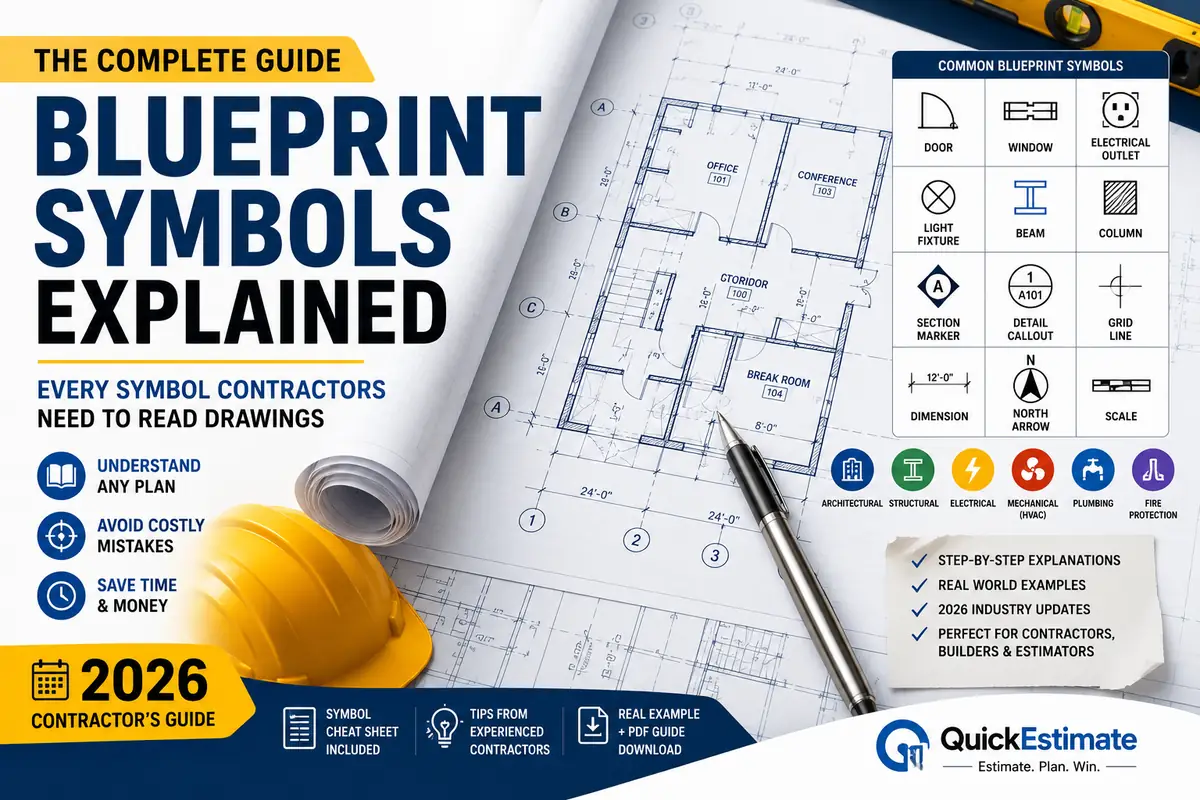
Blueprint Symbols Explained . Hand a rookie a set of construction drawings and watch what happens. They’ll flip through the sheets, nod along, then stall out on something like a hexagon with “GFI” inside it, or a dashed line running along a wall that isn’t actually there. Every trade has its own shorthand, and blueprints are where those shorthands collide on a single sheet — or, more likely now, a single tablet screen.
This guide breaks down blueprint symbols the way a superintendent would explain them to a new hire: discipline by discipline, with the reasoning behind each mark. Whether you’re pulling permits, running a framing crew, or estimating a bid, understanding blueprint symbols is what separates people who can talk about a job from people who can actually build it.
What Are Blueprint Symbols?
With blueprint symbols explained clearly, the confusion disappears: they’re standardized graphic marks — lines, shapes, hatching patterns, and abbreviations — that represent physical building components on a drawing, largely following CSI MasterFormat conventions. A single symbol on a floor plan can stand in for a door, a wall type, an electrical outlet, or a structural column, without the drafter writing a paragraph to describe it.
They exist because construction drawings have almost no room for words. A typical floor plan sheet is already packed with dimensions and notes — if every fixture and assembly needed a text label, the drawing would be unreadable within minutes.
Most symbols trace back to standards from groups like ANSI, the National Institute of Building Sciences, and discipline-specific bodies such as NFPA for fire protection. Firms tweak the specifics slightly, which is exactly why the legend on every sheet matters more than a memorized symbol chart.
Why Blueprint Symbols Explained Correctly Matters
Get a symbol wrong and the mistake doesn’t stay on paper. Misread a wall type as non-rated when it’s actually a two-hour fire-rated assembly, and you’ve got a code violation — discovered during inspection, or worse, after drywall is hung and has to come back down.
On commercial jobs, symbol literacy lets five trades work off the same drawings without a superintendent translating for each crew — the drawings are supposed to speak for themselves.
Estimators depend on symbol accuracy just as much as field crews. A takeoff built from a misread door schedule or uncounted fixture symbol turns into a change order down the line — where profit margins quietly disappear.
How Construction Drawings Are Organized
Before symbols make sense, the drawing set itself needs to make sense — a full document package is organized by discipline, each with its own letter prefix on the sheet numbers.
| Drawing Type | Purpose |
|---|---|
| G — General | Cover sheet, code summary, sheet index |
| C — Civil | Site plan, grading, utilities, drainage |
| A — Architectural | Floor plans, elevations, sections, finishes |
| S — Structural | Foundation, framing, structural details |
| M — Mechanical | HVAC systems, ductwork, equipment |
| P — Plumbing | Water supply, waste, vent piping, fixtures |
| E — Electrical | Power, lighting, low-voltage systems |
| FP — Fire Protection | Sprinkler systems, standpipes, alarm devices |
| ID — Interior Design | Finishes, furniture layouts, millwork |
Every sheet follows a numbering convention — A-101, A-201, A-301 — where the first digit typically indicates sheet type (1 = plans, 2 = elevations, 3 = sections). Once you know that hierarchy, jumping between sheets to cross-reference a detail stops feeling like guesswork.
Understanding the Blueprint Legend
Here’s the thing nobody tells apprentices early enough: symbols aren’t universal law, they’re closer to a dialect. Every drawing set includes a legend — usually on the general notes sheet or cover sheet — defining exactly what each symbol means for that project.
Quick answer: A blueprint legend is a key printed on the drawing set defining every symbol, line type, and abbreviation used — checking it prevents costly misreads on-site, since conventions vary between architects, engineers, and CAD standards.
I’ve seen two firms use a nearly identical hatch pattern for concrete block and rated gypsum board — the only thing separating them was a footnote in the legend. Skip that check, and you’re building the wrong wall.
When reviewing permit drawings, locate the legend before a full read-through. Check it against:
- Line types for existing versus new construction
- Wall hatching patterns and what assembly each represents
- Symbol keys for doors, windows, equipment tags
- Project-specific abbreviations that deviate from industry norms
Architectural Blueprint Symbols
Architectural symbols cover the building as an occupied space — walls, rooms, doors, windows, stairs, finishes. These are the symbols most people picture when they think “blueprint.”
| Blueprint Symbol | Meaning | Where Used |
|---|---|---|
| Solid thick line | Wall (new construction) | Floor plans |
| Dashed line | Wall or object above/below plane, or existing wall to be removed | Floor plans, RCPs |
| Filled triangle in circle | Room/finish tag | Floor plans |
| Circle with number | Door tag | Floor plans, door schedule |
| Hexagon or diamond with letter | Window tag | Floor plans, window schedule |
| Arrow with steps | Stair direction (up/down) | Floor plans |
| Diagonal hatch box | Elevator or shaft | Floor plans |
| Bubble with number/letter | Interior elevation or detail reference | Floor plans |
Room tags show the room name, number, and sometimes finish codes tied to a finish schedule. These aren’t decorative — on a hospital or school project, that code ties directly to required materials like fire-rated ceiling tile or slip-resistant flooring.
Structural Blueprint Symbols
Structural drawings speak a more mathematical dialect than architectural sheets — concerned with what holds the building up, not what it looks like.
Columns show up as filled squares or circles, tagged with a grid reference and size callout (like W8x31). Beams are lines along their span, labeled with size. Footings appear as rectangles or dashed outlines beneath the foundation plan, tagged with a schedule reference like F1 or F2.
Rebar callouts trip up a lot of new estimators. A note like “#5 @ 12″ O.C. EW” means half-inch rebar, spaced twelve inches on center, each way. Get the bar size or spacing wrong and the steel tonnage can be off even when the concrete quantity is fine.
| Blueprint Symbol | Meaning | Where Used |
|---|---|---|
| Filled circle/square | Column | Structural plans |
| Double line with hatch | Beam or girder | Framing plans |
| Rectangle w/ dashed outline | Spread footing | Foundation plans |
| Hooked line symbol | Rebar bend/hook | Structural details |
| Triangle with number | Structural grade/elevation point | Structural plans |
| Zigzag line | Break line (drawing continues) | All structural sheets |
During framing inspections, inspectors cross-check structural drawings against what’s actually nailed and bolted together — hold-down locations, shear walls, and bearing points trace back to the structural set, not the architectural one.
Electrical Blueprint Symbols
Electrical symbols are compact by necessity — a single power plan can have hundreds of devices on it, but once the pattern clicks, they’re among the most consistent symbols in the industry.
| Blueprint Symbol | Meaning | Where Used |
|---|---|---|
| Circle with two lines | Duplex receptacle | Power plans |
| Circle with “GFI” or “WP” | GFCI or weatherproof receptacle | Power plans, wet locations |
| “S” in circle | Single-pole switch | Lighting plans |
| “S3” in circle | Three-way switch | Lighting plans |
| Circle with X | Ceiling-mounted light fixture | Reflected ceiling plans |
| Square with diagonal lines | Junction box | Power plans |
| Rectangle labeled “P” | Electrical panel | Power plans |
| Triangle with “J” | Data/communication jack | Low-voltage plans |
| Dashed line with arrow | Home run to panel | Power plans |
Panel schedules pair with these symbols to give circuit numbers, breaker sizes, and load calculations — tracing a home run symbol back to its panel confirms which breaker feeds which device.
Many contractors mark plan revisions with a contrasting color cloud and a delta symbol, so the crew knows exactly what changed between bid and issued-for-construction sets.
Mechanical (HVAC) Symbols
HVAC drawings look intimidating at first since ductwork symbols vary by supply, return, or exhaust air — each with its own line weight.
| Blueprint Symbol | Meaning | Where Used |
|---|---|---|
| Rectangle with arrow | Supply air duct (direction of flow) | Mechanical plans |
| Rectangle with cross-hatch | Return air duct | Mechanical plans |
| Circle with X pattern | Diffuser/register | Reflected ceiling plans |
| Rectangle with “VAV” | Variable air volume box | Mechanical plans |
| Circle labeled “AHU” or “RTU” | Air handling unit / rooftop unit | Mechanical plans, roof plans |
| Thermostat symbol (T in circle) | Temperature control point | Mechanical plans |
| Dashed rectangle | Ductwork above ceiling (concealed) | Mechanical plans |
Equipment tags matter enormously: an “RTU-1” on the roof plan should match a schedule listing tonnage, electrical requirements, and curb dimensions. Experienced estimators cross-check every tag against its schedule before pricing, since a mismatch can mean an entirely different piece of equipment than specified.
Plumbing Symbols
Plumbing drawings separate cleanly into supply (water in) and waste/vent (water and air out), and the symbols reflect that split.
| Blueprint Symbol | Meaning | Where Used |
|---|---|---|
| Solid line labeled “CW” | Cold water supply | Plumbing plans |
| Solid line labeled “HW” | Hot water supply | Plumbing plans |
| Dashed line labeled “V” | Vent piping | Plumbing plans |
| Solid line labeled “W” or “SS” | Waste or sanitary sewer line | Plumbing plans |
| Circle labeled “FD” | Floor drain | Plumbing plans |
| Rectangle labeled “WH” | Water heater | Plumbing plans |
| Triangle or hexagon with fixture outline | Plumbing fixture (sink, toilet, etc.) | Plumbing plans, fixture schedule |
| “CO” in circle | Cleanout | Plumbing plans, site utility plans |
Pipe sizing is written directly on the line — 3″ SS or 3/4″ CW — and slope callouts (1/4″ per foot) tell the installer how much fall to build in. Miss one and you get standing water in a line that should drain on gravity alone.
Civil Drawing Symbols
Civil symbols cover everything outside the building footprint — grading, utilities, roads, property boundaries — and tend to intimidate architectural-side readers since they lean on contour lines and survey notation.
| Blueprint Symbol | Meaning | Where Used |
|---|---|---|
| Solid contour line with elevation label | Existing grade elevation | Grading plans |
| Dashed contour line | Proposed grade elevation | Grading plans |
| Triangle labeled “BM” | Benchmark (survey reference point) | Site plans |
| Line with alternating dashes | Property line | Site plans, plats |
| Arrow with “FL” label | Flow line/drainage direction | Grading and drainage plans |
| Circle labeled “MH” | Manhole | Utility plans |
| Hydrant symbol (small circle with cross) | Fire hydrant | Site and utility plans |
| Dashed line labeled “UGE” | Underground electric | Utility plans |
Civil engineers rely on spot elevations — small crosses or dots with a number — for exact grade points where contour lines alone aren’t precise enough. If you’re pricing sitework, those spot elevations are what cut-and-fill calculations are built on.
Fire Protection Symbols
Fire protection drawings get their own discipline since life-safety systems are regulated separately, often referencing NFPA standards directly on the sheet.
| Blueprint Symbol | Meaning | Where Used |
|---|---|---|
| Circle with cross pattern | Sprinkler head (pendant) | Fire protection plans |
| Circle with cross, upward tick | Sprinkler head (upright) | Fire protection plans |
| Square with “F” | Fire alarm pull station | Life safety plans |
| Circle with bell symbol | Fire alarm horn/strobe | Life safety plans |
| Thick line labeled “FP” | Fire protection main | Fire protection plans |
| Rectangle labeled “FDC” | Fire department connection | Site plans, fire protection plans |
| Circle labeled “SV” | Sprinkler system valve | Fire protection plans |
During plan review, code officials pay close attention to sprinkler head spacing and coverage area — symbols alone won’t confirm compliance, but combined with the hazard classification, they show whether the design meets NFPA 13 requirements.
Door & Window Symbols
Doors and windows get tagged individually because every opening usually has its own hardware, fire rating, or glazing requirement buried in a schedule elsewhere in the set.
Quick answer: Door symbols on floor plans show as a quarter-circle arc representing the swing path from the hinge point, paired with a numbered tag linking to the door schedule for size, material, fire rating, and hardware. Window symbols appear as a break in the wall line (sometimes with a sill line), with a tag referencing the window schedule for glazing type, U-factor, and rough opening dimensions.
Wall Symbols
Wall types are communicated through line weight and hatch pattern, which is exactly why the legend is non-negotiable reading before a takeoff.
A single heavy line usually means a standard framed wall; a double line with cross-hatching often means masonry or concrete block. Walls are frequently tagged with a letter or number — “W1,” “W2” — referencing a wall type schedule showing the full assembly: stud size, insulation, gypsum board layers, fire rating.
Fire-rated walls get called out specifically, often with a bold line and a note like “1-HR” along the wall. This isn’t minor — a corridor wall built as a standard partition instead of the rated assembly it calls for is a life-safety failure inspectors will catch.
Section & Elevation Symbols
Sections and elevations pull the building out of plan view, showing it from the side or in a vertical slice. Finding your way between these views depends on recognizing the reference symbols.
A section symbol on a floor plan looks like a circle or box with a line cutting through the plan, an arrow showing view direction, and a reference number pointing to the sheet where that section is drawn. Elevation symbols work similarly — a small triangle or arrow tag points toward the building face being shown, referencing the elevation sheet.
Interior elevation symbols usually appear as a circle divided into quadrants, each showing a sheet and elevation number for that wall. Once you’re comfortable following these tags, jumping to the exact section you need takes seconds instead of flipping through the whole set.
Detail Callout Symbols
Detail callouts are how a drawing set avoids repeating the same information twenty times. Instead of redrawing a window head condition on every elevation, the drafter places a small bubble — a number on top, a sheet reference on the bottom — pointing to the spot where that detail applies. A callout reading “4 / A-501” means detail 4 on sheet A-501 explains exactly what’s happening at that point in the wall, roof, or floor assembly.
Shop drawings extend this logic further, breaking manufacturer-specific components into fabrication-level detail the contract drawings only gesture at — checked against architectural details before fabrication, catching conflicts before material shows up on-site.
Grid Lines
Grid lines are a building’s coordinate system. Vertical lines are usually labeled with numbers, horizontal with letters (or vice versa), creating intersections like “Grid C-4” that every trade uses as a shared reference point.
Structural columns, beams, and load-bearing walls almost always align to grid lines, making them the fastest way to communicate a location. Tell a crew “check the header at Grid C-4” and everyone knows exactly where to look.
Dimensions
Dimension lines show the distance between two points, capped with tick marks, arrows, or diagonal slashes depending on office standard. Reading them correctly means knowing what’s being measured — face of stud, face of finish, or centerline — since a half-inch difference in convention adds up fast across a long wall run.
Overall building dimensions run along the outside of the plan, with room and opening dimensions nested inside. Extension lines project from the wall out to the dimension line and should never touch the object being measured — that gap is intentional.
A good field habit: verify a dimension by adding up individual room and wall dimensions and checking the total against the overall building dimension. If they don’t match, the drawing has an error — better to catch it on paper than after a wall is framed wrong.
North Arrow
Every plan sheet includes a north arrow, usually in a corner, showing true or project north. Project north is worth knowing specifically — architects often rotate the building slightly for layout convenience and use a “project north” that doesn’t exactly match true north, noting the actual compass bearing separately.
This matters more than it sounds: site orientation affects everything from solar heat gain to which windows get afternoon sun. Cross-checking the north arrow between civil and architectural sheets is a five-second habit that prevents an expensive misunderstanding.
Scale
Scale tells you the ratio between the drawing and the real building — 1/4″ = 1′-0″ means every quarter inch on paper equals one real-world foot. Architectural and engineering scales use different graduations, and mixing them up is a classic beginner mistake that produces wildly wrong measurements.
Digital drawings complicate this: on a PDF, “scale” only holds true at 100% zoom, since screen zoom doesn’t respect the printed scale bar the way a physical ruler does. Most takeoff software calibrates scale using a known dimension on the sheet instead of trusting the printed note blindly.
Quick answer: Blueprint scale is the ratio between drawing size and actual building size, commonly 1/4″ = 1′-0″ for floor plans or 1″ = 20′ for site plans. Always confirm using a printed dimension rather than assuming a digital PDF displays at true scale.
Common Blueprint Abbreviations
Abbreviations show up everywhere, packed into notes and dimension strings where full words would clutter the sheet. Here’s a working reference of the ones that show up on nearly every project.
| Blueprint Abbreviation | Full Meaning |
|---|---|
| A.F.F. | Above Finished Floor |
| C.J. | Control Joint |
| C.L. | Centerline |
| C.O. | Cleanout |
| DN | Down |
| E.J. | Expansion Joint |
| EXT | Exterior |
| FDN | Foundation |
| FIN | Finish |
| GC | General Contractor |
| GYP BD | Gypsum Board |
| INT | Interior |
| MIN/MAX | Minimum/Maximum |
| N.I.C. | Not In Contract |
| O.C. | On Center |
| R.O. | Rough Opening |
| TYP | Typical |
| U.O.N. | Unless Otherwise Noted |
| V.I.F. | Verify In Field |
| W/ | With |
That last one — V.I.F. — is worth memorizing above almost any other. It’s the drawing set telling you, in two letters, “confirm this against reality before you cut anything.” Ignoring it is how a well-drawn detail turns into a field conflict.
Real Blueprint Reading Example
Theory only gets you so far. Here’s how an experienced reader actually walks a sheet.
Say you’re looking at a floor plan for a small commercial tenant space. Start at the title block — sheet number, revision date, scale — then the legend, checking wall hatch patterns against the wall type schedule. Trace the grid lines to orient yourself, noting where structural columns land relative to interior partitions.
Inside the room, read the door tag and cross-reference the door schedule for the fire rating — critical next to an exit corridor. Overhead, the reflected ceiling plan shows fixture and diffuser locations, cross-checked against electrical and mechanical so nothing collides above the ceiling grid.
Finally, check for detail callout bubbles near tricky conditions and flip to that detail before assuming you understand the full condition. Done in order, this is how a five-minute read prevents a five-hour field problem.
Common Mistakes Beginners Make
New estimators and apprentices tend to trip over the same handful of errors, most from rushing past the legend rather than any real lack of skill.
Confusing existing-to-remain lines with new construction lines is the most common one — both often use similar dashed or solid conventions, and only the legend clarifies which is which. Another frequent slip: assuming symbol standards are identical across every project, when a symbol on a small residential set can mean something entirely different on a hospital project using a national A/E standard.
People also skip cross-referencing schedules, treating the plan symbol as the complete picture instead of a pointer to more detail. It’s also common to misread scale on a resized sheet whose scale note wasn’t updated — check a known dimension if something feels off.
Professional Tips From Experienced Contractors
A few habits separate people who read drawings fluently from people still translating symbols in their head.
Cross-check every discipline against the others before starting work — architectural, structural, mechanical, electrical, and plumbing should agree on wall locations, ceiling heights, and equipment placements. When they don’t, flag it through an RFI rather than guessing which set is correct.
Keep a running list of project-specific symbol deviations on larger jobs with multiple consultants, and don’t treat the legend as a one-time read — revisit it whenever a revised set comes through, since legends do change between issuances.
Digital Blueprints vs Paper Blueprints
Paper sets still show up for field marking where a tablet isn’t practical, but digital blueprints are now standard for cross-trade coordination — revision clouds, RFI markups, and as-built annotations live directly in the file, timestamped and attributed to whoever made the change.
The tradeoff is discipline: everyone needs the same file version, or you get exactly the confusion digital tools were supposed to fix — one crew building off Revision 3 while another reads Revision 4. A clear file-naming protocol at kickoff avoids that.
How BIM Has Changed Blueprint Reading
Building Information Modeling didn’t replace blueprint symbols so much as change where they come from. In a BIM workflow, 2D symbols are generated automatically from a 3D model’s component data — a door symbol is tied to an actual door object, with size, rating, and hardware baked into the model itself, not just a note that could drift out of sync. Clash detection, run before construction begins, catches mechanical-versus-structural conflicts that used to only surface once ductwork was already going in above an unaccounted-for beam.
Autodesk’s Revit dominates architectural and MEP coordination, and buildingSMART’s open IFC standard lets models from different software talk to each other — BIM-derived symbols tend to be more reliable, since they come from one coordinated source rather than being redrawn sheet by sheet.
2026 Industry Updates
A few shifts worth knowing heading into 2026. Model-based deliverables are increasingly requested alongside — or instead of — traditional 2D sheet sets on larger commercial projects, especially where owners want a facilities-management-ready model at closeout, which pushes symbol accuracy further upstream since a mistake in the model propagates to every sheet generated from it.
Cloud-based common data environments have also become standard on multi-trade jobs, replacing emailing PDF sets back and forth and cutting down the “which version is current” problem — drawings increasingly built to answer questions before a reviewer has to ask.
Frequently Asked Questions
What’s the difference between a floor plan symbol and an elevation symbol?
Floor plan symbols show a top-down view — walls, doors, fixtures as seen from above. Elevation symbols show a straight-on side view, with vertical elements like window heights and roof lines.
What does a dashed line mean on a blueprint?
It depends on context: an object above or below the plan cut, an existing wall scheduled for demolition, or a concealed element like ductwork above a ceiling. Always verify against that sheet’s legend rather than assuming from a past project.
Do I need to know these symbols if I use takeoff software?
Yes, arguably more than ever. Software speeds up measurement, but it can’t catch a symbol misread as the wrong fixture or wall assembly — that judgment still comes from the person operating it.
What should I do if a symbol isn’t in the legend?
Check other sheets first — legends sometimes split across the cover sheet and discipline-specific sheets. If it’s genuinely undocumented, don’t guess: submit an RFI. It’s far cheaper than rework based on a misread mark.
Final Thoughts
Blueprint symbols aren’t something you memorize from a chart. They’re a language, and fluency comes from repetition — reading real sets, catching your own misreads, checking the legend before assuming anything. The contractors who move fastest through a drawing set aren’t the ones who memorized the most symbols; they’re the ones with a reliable process: legend first, cross-reference always, verify in the field.
Keep this guide open next to your next set of drawings — over time you won’t need it, but everyone needs it at some point.